PUGAUGE Hardware: Unterschied zwischen den Versionen
(Die Seite wurde neu angelegt: „{{PUGAUGE Hardware Summary}} == Build notes == === Connection of ATmega6490 === In the first development version all circuitry is mounted on a solderless br…“) |
Keine Bearbeitungszusammenfassung |
||
| Zeile 1: | Zeile 1: | ||
{{PUGAUGE Hardware Summary}} | {{PUGAUGE Hardware Summary}} | ||
== Build notes == | === Build notes === | ||
=== Connection of ATmega6490 === | ==== Connection of ATmega6490 ==== | ||
In the first development version all circuitry is mounted on a solderless breadboard: | In the first development version all circuitry is mounted on a solderless breadboard: | ||
| Zeile 45: | Zeile 45: | ||
{{TableEnd}} | {{TableEnd}} | ||
=== Serial-USB Adapter, connected to TXD/RXD of UART0 of ATmega6490 PLUS Auto-Reset-Circuit using DTR of Serial-USB === | |||
{{TableBegin}} | {{TableBegin}} | ||
| Zeile 60: | Zeile 60: | ||
| 30 || 5 | | 30 || 5 | ||
{{TableEnd}} | {{TableEnd}} | ||
=== Optional Debug-Assist Serial-USB-Adapter, connected to a GPIO Port driven by Software-UART === | |||
This is an output-only software/bit-banging asynchronous serial output used for outputting debug information. | |||
The serial output of this interface is connected to GPIO Port PB6 and may be hooked up to an additional Serial-USB adapter. | |||
This debug output port is served by the [[PUGAUGE Software#PUGAUGE Debug Library|PUGAUGE debug library]], which also provides a few convenience debug output functions and shortcut macros which can be enabled or disabled at compile time additional to route debug output to either the {{PUGAUGE}} LCD and/or the debug serial port. | |||
=== TQFP-100 Breakout board === | === TQFP-100 Breakout board === | ||
Aktuelle Version vom 2. Jänner 2019, 22:03 Uhr
Overview
- 8-Character Segmented LCD 14-segment Display
- Atmel AVR ATmega6490A AVR microcontroller
- Atmel ISP Connection
- Arduino Upload Serial Interface
- A Status LED on MCU port PB0
Build notes
Connection of ATmega6490
In the first development version all circuitry is mounted on a solderless breadboard:
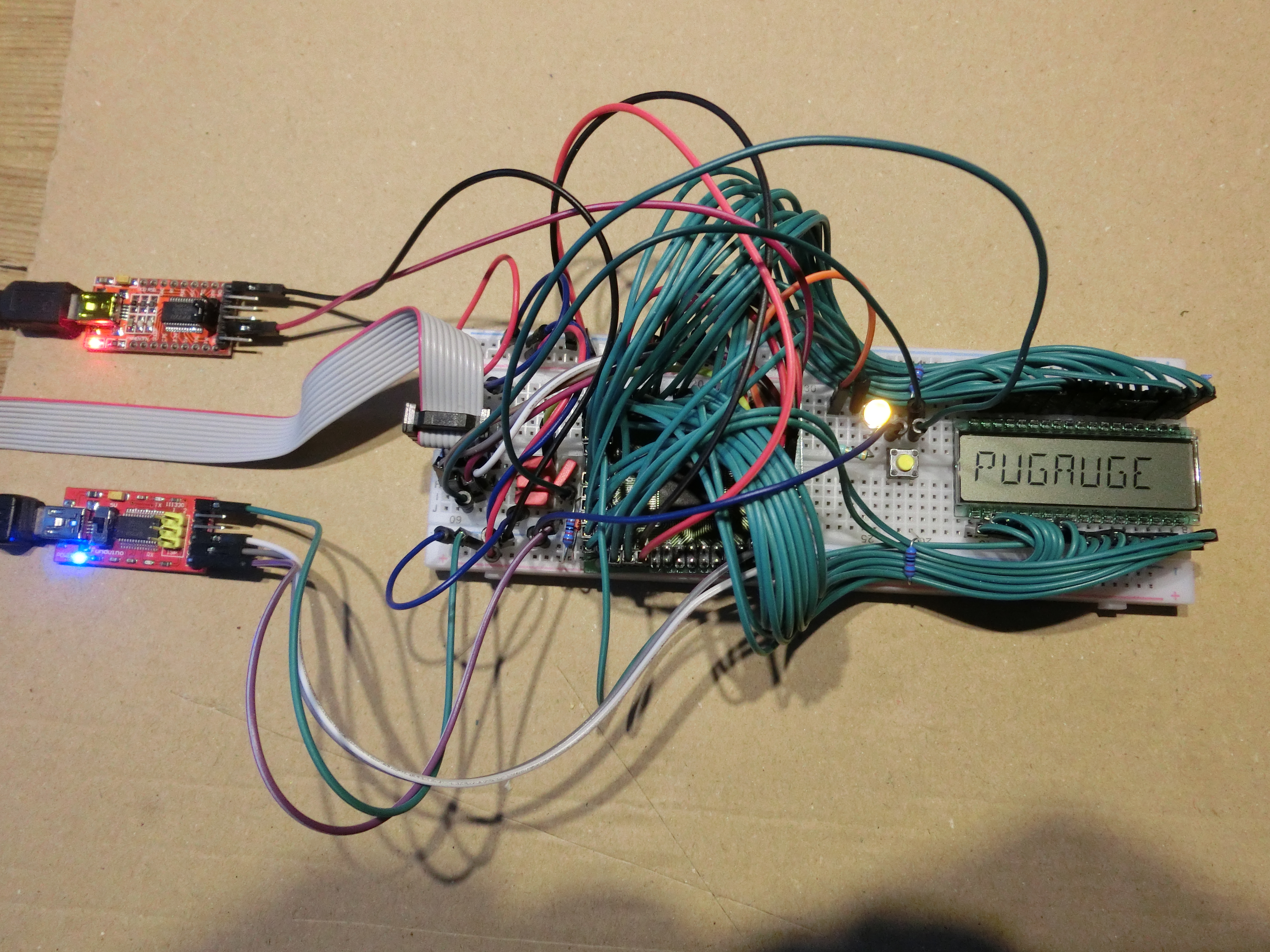
- The ATmega6490 is mounted on the BBR.
- LCD-Voltage Buffer Capacitor: 3x220nF FKC in parallel from ATmega6490 Pin 1 / BBR Pin 76 to GND
- System Status LED: Port line PB0 (ATmega6490 Pin 19 / BBR Pin 94) to 330 Ohm to yellow LED to GND
- In-System-Programmer (IST) USPasp connected to 10-pin 2x5 100mil-spaced Connector:
See also http://nerdyelectronics.com/usbasp-tutorial/ :
                                                           Connector seen on board pins
USBasp pin number USBasp pin MCU Pin                          +---+---+---+---+---+
1 	          MOSI       MOSI                             | 2 | 4 | 6 | 8 |10 |
5                 Reset      Reset                            +---+---+---+---+---+
7                 SCK        SCK                              | 1 | 3 | 5 | 7 | 9 |
9                 MISO       MISO                             +---+--++---++--+---+
10                GND        GND                                     +-----+
2                 Vcc        Vcc                           NOTE1: the USBasp ribbon cable has a RED marking on the wire going to in 1
                                                                  thus, it should be on the LEFT side of above connector!
                                                           NOTE2: the USBasp ribbon cable connector has a protrusion in the near pin 5. Look for this to be sure!
| Signal name | description | 10-pin-conn pin number | ATmega6490 pin name | ATmega6490 pin number | BBR pin number |
|---|---|---|---|---|---|
| MOSI | data from programmer to MCU | 1 | MOSI | 21 | 96 |
| Reset | reset pulse to MCU | 5 | Reset | 30 | 5 |
| SCK | serial clock to MCU | 7 | SCK | 20 | 95 |
| MISO | data from MCU to programmer | 9 | MISO | 22 | 97 |
| GND | Ground reference | 10 | GND | 99,11,32,81 | 74,86,7,56 |
| VCC | +5V supply from programmer | 2 | VCC | 100,10,31,80 | 75,85,6,55 |
Serial-USB Adapter, connected to TXD/RXD of UART0 of ATmega6490 PLUS Auto-Reset-Circuit using DTR of Serial-USB
| Signal name | description | FT323-adapter pin | ATmega6490 pin name | ATmega6490 pin number | BBR pin number |
|---|---|---|---|---|---|
| GND | Ground reference | GND | GND | ||
| TXD | data from USB to MCU | TXD | RXD/PCINT0/PE0 | 2 | 77 |
| RXD | data from MCU to USB | RXD | TXD/PCINT1/PE1 | 3 | 78 |
| DTR | DataTerminalReady from USB | DTR | 100nF Capacitor to "Reset"-Pin PLUS: pullup-10k-Resistor to +5V parallel to 1N4148Diode Cathode to +5V, Anode to Reset PLUS "RESET"Button to GND |
30 | 5 |
Optional Debug-Assist Serial-USB-Adapter, connected to a GPIO Port driven by Software-UART
This is an output-only software/bit-banging asynchronous serial output used for outputting debug information.
The serial output of this interface is connected to GPIO Port PB6 and may be hooked up to an additional Serial-USB adapter.
This debug output port is served by the PUGAUGE debug library, which also provides a few convenience debug output functions and shortcut macros which can be enabled or disabled at compile time additional to route debug output to either the PUGAUGE LCD and/or the debug serial port.
TQFP-100 Breakout board
When soldering the AVR6490 Chip in the TQFP-100 case to it's breakout board, I made an error:
I turned it 90 degrees to the right. Therefore Pin 1 of the chip appears at Pin 76 of the breakout board.
The algorithm to find the BBR pin when knowing the pin number on the TQFP-100 package of the ATmega6490 is:
BBR-pin = (TQFP-pin + 75) MOD 100
There will be a translation table on the PUGAUGE Tables page.
Connection from the D301 LCD to the PUGAUGE MCU is documented on the PUGAUGE Tables page.