PUGAUGE - Low Power Display Processor: Unterschied zwischen den Versionen
Keine Bearbeitungszusammenfassung |
|||
| (9 dazwischenliegende Versionen desselben Benutzers werden nicht angezeigt) | |||
| Zeile 1: | Zeile 1: | ||
{{Image|/public/Projekte/PUGAUGE/Hardware/PUGAUGE_BBD-002.JPG|height=400px}} | |||
The PUGAUGE is intended to be a base platform for devices to display Information in an environment where low power requirements are mandatory. | The PUGAUGE is intended to be a base platform for devices to display Information in an environment where low power requirements are mandatory. | ||
| Zeile 10: | Zeile 11: | ||
== Hardware == | == Hardware == | ||
{{PUGAUGE Hardware Summary}} | |||
== Software == | == Software == | ||
| Zeile 21: | Zeile 21: | ||
Therefore, an extension to the Arduino IDE is developed to allow the PUGAUGE being selected as a board type in the Arduino IDE. This should not be too complicated, as the PUGAUGE processor is an Atmel AVR processor closely related to the Atmel AVR processors used in the Arduino UNO and MEGA. | Therefore, an extension to the Arduino IDE is developed to allow the PUGAUGE being selected as a board type in the Arduino IDE. This should not be too complicated, as the PUGAUGE processor is an Atmel AVR processor closely related to the Atmel AVR processors used in the Arduino UNO and MEGA. | ||
Additionally the ''''' | Additionally the '''''atmegaboot''''' bootloader for the Arduino is being modified to run on the PUGAUGE and allow Arduino sketches to be uploaded onto the PUGAUGE. | ||
For the time being, a board/platform package is available with working minimal build and upload configuration: | |||
{{TableBegin}} | {{TableBegin}} | ||
! | ! Feature !! Status PUGAUGE6490 !! Status PUGAUGE1284 | ||
|- | |- | ||
| | | atmegaboot customization || complete || {{tbc}} | ||
|- | |- | ||
| | | build configuration || complete || {{tbc}} | ||
|- | |- | ||
| | | upload configuration || complete || {{tbc}} | ||
|- | |- | ||
| | | digital port customization || {{tbc}} || {{tbc}} | ||
|- | |- | ||
| | | analog input customization || {{tbc}} || {{tbc}} | ||
{{ | |||
{{ | |||
|- | |- | ||
| | | PWM "analog" output customization || {{tbc}} || {{tbc}} | ||
|- | |- | ||
| | | hardware serial core || {{tbc}} || {{tbc}} | ||
|- | |- | ||
| | | software serial core || {{tbc}} || {{tbc}} | ||
|- | |- | ||
| | | PUGAUGE LCD as standard Arduino library || {{tbc}} || {{tbc}} | ||
{{TableEnd}} | {{TableEnd}} | ||
To add the PUGAUGE core to your Arduino installation, add the following URLs to the arduino board manager: | |||
* <code>https://github.com/esp8266/Arduino/releases/download/2.4.0-rc2/package_esp8266com_index.json</code>, | |||
* <code>http://scherer3002.duckdns.org/public/public/Projekte/PUGAUGE/downloads/package_pucon_pugauge_index.json</code> | |||
{{tbc}} | |||
=== Application === | |||
A special LCD library is being developed that provides easy access to the on board LCD ( 8 characters, 14 segments plus decimal point and apostroph). | |||
{{tbc}} | |||
== Font made visible == | == Font made visible == | ||
Likewise, a graphic depiction of the 14-Segment font is to be found on the [[PUGAUGE Tables]] page. | Likewise, a graphic depiction of the 14-Segment font is to be found on the [[PUGAUGE Tables]] page. | ||
Aktuelle Version vom 13. Juni 2020, 11:38 Uhr
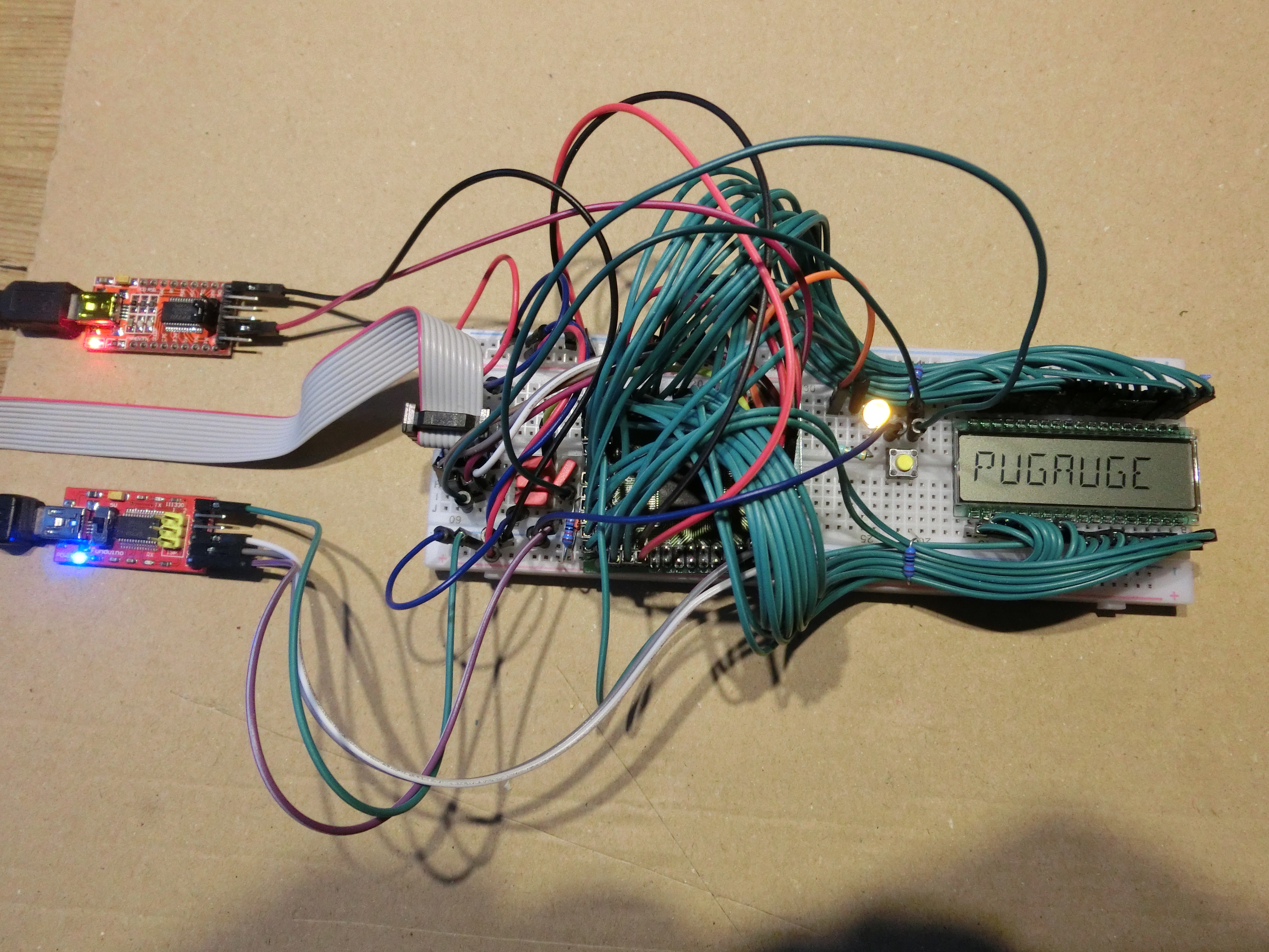
The PUGAUGE is intended to be a base platform for devices to display Information in an environment where low power requirements are mandatory.
Examples are:
- Bike computers
- Thermometers
- mobile measurement devices
Hardware
Overview
- 8-Character Segmented LCD 14-segment Display
- Atmel AVR ATmega6490A AVR microcontroller
- Atmel ISP Connection
- Arduino Upload Serial Interface
- A Status LED on MCU port PB0
Software
Platform
The PUGAUGE is intended to be Arduino-compatible. The application software shall benefit from the ease of use, familiarity of many developers and availability of many libraries for sensors and other peripherals.
Therefore, an extension to the Arduino IDE is developed to allow the PUGAUGE being selected as a board type in the Arduino IDE. This should not be too complicated, as the PUGAUGE processor is an Atmel AVR processor closely related to the Atmel AVR processors used in the Arduino UNO and MEGA.
Additionally the atmegaboot bootloader for the Arduino is being modified to run on the PUGAUGE and allow Arduino sketches to be uploaded onto the PUGAUGE.
For the time being, a board/platform package is available with working minimal build and upload configuration:
| Feature | Status PUGAUGE6490 | Status PUGAUGE1284 |
|---|---|---|
| atmegaboot customization | complete | (zu ergänzen) |
| build configuration | complete | (zu ergänzen) |
| upload configuration | complete | (zu ergänzen) |
| digital port customization | (zu ergänzen) | (zu ergänzen) |
| analog input customization | (zu ergänzen) | (zu ergänzen) |
| PWM "analog" output customization | (zu ergänzen) | (zu ergänzen) |
| hardware serial core | (zu ergänzen) | (zu ergänzen) |
| software serial core | (zu ergänzen) | (zu ergänzen) |
| PUGAUGE LCD as standard Arduino library | (zu ergänzen) | (zu ergänzen) |
To add the PUGAUGE core to your Arduino installation, add the following URLs to the arduino board manager:
https://github.com/esp8266/Arduino/releases/download/2.4.0-rc2/package_esp8266com_index.json,http://scherer3002.duckdns.org/public/public/Projekte/PUGAUGE/downloads/package_pucon_pugauge_index.json(zu ergänzen)
Application
A special LCD library is being developed that provides easy access to the on board LCD ( 8 characters, 14 segments plus decimal point and apostroph).(zu ergänzen)
Font made visible
Likewise, a graphic depiction of the 14-Segment font is to be found on the PUGAUGE Tables page.