Projekt TekRep7k: Unterschied zwischen den Versionen
Keine Bearbeitungszusammenfassung |
|||
| (19 dazwischenliegende Versionen desselben Benutzers werden nicht angezeigt) | |||
| Zeile 1: | Zeile 1: | ||
On ebay I found a [[Tektronix 7623]] Oscilloscope "for Parts" for only 30.- EUR. The 7623 is not the top-of-the-line of the Tektronix 7000 Series and the thing might have been dead as a doornail but for 30 EUR I decided to take the risk and got it sent to me. | |||
In my hardware time in the 1980's the Tek 7000 line was sort of the holy grail of oscilloscopes with all high quality features, modular plug-in architecture and a On-Screen readout. Of course it came with the associated steep price tag, so being able to own such a beast even after more that 30 Years and even having to repair it myself sounded very attractive. | |||
The interesting feature of the 7623 is that it is a CRT variable storage oscilloscope, a Tek speciality and there also only found in 2 models. | |||
At first power-on, the only parts showing activity was the cooling fan and the graticule lighting. No Beam on the CRT, no lighted knobs. | |||
So, into the repair job. The 7623 being a product of the 1980s helps with DIY repair, because: | |||
* Most parts are more-or-less standard through-hole low integration parts like single transistors and SSI TTL 74xx ICs | |||
* The size of the parts compared to today's SMD components renders them recognizable to even a myopic 50+ person like myself | |||
* The vendors at that time, especially the likes of Tektronix, made tremedously good maintenance manuals, containing not only calibration instructions but also complete schematics, layout drawings and explanatory texts about how the product is supposed to work, down to each individual transistor | |||
Additionally, [http://w140.com/tekwiki/images/0/0c/Email_address.gif Kurt] at [[http://w140.com/tekwiki/ TekWiki] ([http://w140.com/tekwiki/wiki/7623 The Tekwiki 7623 Page]) did and still does an incredible job in collecting and documenting all things Tektronix. | |||
== Resources == | |||
* <html><a href="/public/public/Hardware/MessWerkZeuge/Tektronix_7000">Files</a></html> | |||
== The repair log == | |||
=== 02.11.2015 === | |||
Openening the case revealed the first bad news: | |||
* The vertical Amplifier board had clearly seen a previous bad repair job replacing one of the 2 special ceramic high power resistors | |||
* The fine mains voltage selector which allows (in the 220V position of the coarse voltage selector) to select between mains voltages of 220V/230V and 240V was in the 220V position, which, considering that the Austrian power grid delivers 230V since a few years, produces a 5% to 10% higher input voltage to the Power Supply boards ( as the Power Supply is purely linear with a real big and heavy transformer) | |||
Measuring the 1,4kV test point on the High Voltage (HV) Supply board revealed that the high voltages were not present. | |||
The 2Afast Fuse feeding the HV board with 15 VDC unregulated had been blown and already replaced by a similar one, but being in Europe and 32x6mm Fuses not available, by a 15x4mm Fuse soldered onto the defective bigger one. Unfortunately, the replacement Fuse also was blown. | |||
Fortunately, I could get a pack of 2Afast 32x6mm Fuses at {{Conrad}}. | |||
Additionally, disassembling the HV board showed a desintegrated 10uF / 60V electrolytic capacitor, which I replaced. | |||
The HV board consists of an oscillator, built from standard 2N3055 transistors and a transformer with following voltage multiplier. To be safe I got me some 2N3055s, which I did not need yet because testing them showed them appearently fine. | |||
Supplying the HV board with 15V did not start the oscillator, therefore no HV. | |||
Interestingly, touching a point on the base of one of the oscillator transistors with a multimeter probe cable seemed to start the oscillator, although the sound made by the transformer indicated it being not very happy. Removing the probe let the osciallator die again. | |||
Sadly, when letting the oscillator run a longer time, the +130V supply seemed to have died: the Fuse in the 130V line was blown and the excess current still stayed even when disconnecting everything from the LV PS board. | |||
=== 09.11.2015 === | === 09.11.2015 === | ||
| Zeile 7: | Zeile 51: | ||
{| | {| | ||
|- | |- | ||
| {{T7623Img|007_Start_Of_BotchedOn_Mystery_Wire.JPG|atts=height=300px}} | | {{T7623Img|Disassembly_Repair_HV-board_20151027/007_Start_Of_BotchedOn_Mystery_Wire.JPG|atts=height=300px}} | ||
| Starting at the Low Voltage Supply board | | Starting at the Low Voltage Supply board | ||
* blue wire from Pin #4 of Connector P900 - +5V | |||
* violet wire from Pin #7/8 of Connector P900 - GND | |||
|- | |||
| {{T7623Img|Disassembly_Repair_HV-board_20151027/009_Destination_Of_Mystery_Wire_P10_of_Interconn_Board.JPG|height=300px}} | |||
| ... up to P10 of the Main Interface Board: | |||
* blue Wire to pin #2 of P10 | |||
* violet wire to pin #1 of P10 | |||
P10 has following Pinout: | |||
* Pin #1 (marked with triangle) - Pin 9A of all Plug-In Connectors, named "+5V Lights" | |||
* Pin #2 Pin 14A of all Plug-In Connectors, named "Lights Common" | |||
|- | |- | ||
| {{T7623Img| | | {{T7623Img|Manual/Tek7623UsrManMainInterfaceSchematic.png|height=400px}} | ||
| | | Schematic of the Main Interface Board | ||
|- | |- | ||
| {{T7623Img| | | {{T7623Img|Manual/Tek7623UsrManLVPSSchematic.png|height=400px}} | ||
| | | Schematic of the LV PS Board | ||
|} | |} | ||
=== 20.11.2015 === | |||
To be sure, I ordered some of the more frequently used parts that were still available on AliExpress or wih {{Conrad}}: | |||
* 2N5551 - 20 Pcs | |||
* 2N2905 - 20 Pcs | |||
* 2N2920 - 10 Pcs (dual transistor in TO39 package) | |||
* CA3045 (transistor array in DIL14 package) - 3 Pcs | |||
=== 05.12.2015 === | |||
The power transistors of the LV PS board are Tek special and 2 different part numbers but the service manual declares both of thiese parts as 2N3055 compatible. | |||
However, testing them revealed the at least superficially OK (hFE between 40 and 100). | |||
=== 09.12.2015 === | |||
Investigating the LV PS board showed Q872 to be blown. It being a SE7056 and no replacement type specified I thought a MPSA42 could also do the job. So I ordered 20 of these at {{Conrad}}. | |||
=== 18.12.2015 === | |||
* MPSA42 have arrived | |||
* replaced Q872 with an MPSA42. No improvement | |||
* replaced Q869 with an 2N5551. No change. | |||
* However, -50V produces output voltage, although too high (approx. -60V) | |||
*: I suspect a previous owner had it connected to 230V AC or 240V AC but the fine voltage selector was to the lowest of 3 settings. | |||
=== 26.12.2015 === | |||
* -50V can be adjusted by R861 from -60V thru -52V, unfortunately not to -50V ... | |||
* Page [[Tektronix 7623 Manual]] contains selected parts of the 7623's operators manual, also to be linked from other parts. | |||
=== 04.01.2016 === | |||
* Re-Seating all Transistors on the LV-Supply Board Succeeded in completely working LV-Supply, '''HOORAY''' | |||
* I had bought a bunch of CA3045 chips in case the one on the LV-Supply was damaged | |||
*: to check them, I replaced the CA3045 on the LV-Supply by one of the newly acquired => Works the same! | |||
* HV-Supply works too ( having replaced the exploded Cap by a 22uF one) ! | |||
* after re-assembly, there are 4 connections unconnected because I did not document them at disassembly, '''DAMN!''' | |||
* However, the CRT shows a beam, albeit out of focus | |||
* Tracing the wires shows that two of the open connections are to go to the HV board, which is a pain in the backside because the HV-supply is so deep inside the oscilloscope | |||
*: One of the 2 connections, however, connects the focus-pot | |||
*: The other (P1245 of HV-Supply) connecting 600V to the Storage Control Board (A15) | |||
* Unfortunately, connecting these 2 results resulted in: | |||
** No CRT picure at all | |||
** The HV-Supply case, doubling as the heatsink for the HV primary oscillator transistors, becoming unbearingly hot | |||
** HV testpoint voltage dropping from ~614V (should be 700V according to manual) to 145V | |||
* Disconnecting the cable from P1245 improved things: HV supply voltages back to normal, CRT beam back there, focus control working | |||
* '''TODO:''' find out the cause of the error (most probably another shorted semiconductor) | |||
=== 05.01.2016 === | |||
* Connected a Probe to the 7A18s inputs: Success! | |||
** Voltage calibration seems to be off because 4V calibrator show up only as 3.6 divisions at 1V/Div amplifier setting | |||
* Sweep frequency seems OK according to calibrator display | |||
* Delayed Sweep looks OK | |||
* Now to the 2 missing connections: Tracing finds: | |||
** the longer, coax with blue/white coating connects to the "REMOTE ERASE IN" back panel connector, leading to P1764 on A15 - "Cal & Storage Circuit Board" | |||
** the shorter, coax with green/white coating connects to J1047 - "EXT SS RESET IN" back panel connector, leading to P45 on A1 - "Main Interface Board" | |||
* These resolved, there are 3 issues, put on the backburner for now: | |||
*# get storage to work, which is broken because of the short circuit in the 600V-line | |||
*# resolve the "miracle wire" issues. I removed the miracle wire because it seemed wrong | |||
*# readout does not work for the time being, root cause still unknown | |||
Aktuelle Version vom 15. Jänner 2026, 20:47 Uhr
On ebay I found a Tektronix 7623 Oscilloscope "for Parts" for only 30.- EUR. The 7623 is not the top-of-the-line of the Tektronix 7000 Series and the thing might have been dead as a doornail but for 30 EUR I decided to take the risk and got it sent to me.
In my hardware time in the 1980's the Tek 7000 line was sort of the holy grail of oscilloscopes with all high quality features, modular plug-in architecture and a On-Screen readout. Of course it came with the associated steep price tag, so being able to own such a beast even after more that 30 Years and even having to repair it myself sounded very attractive.
The interesting feature of the 7623 is that it is a CRT variable storage oscilloscope, a Tek speciality and there also only found in 2 models.
At first power-on, the only parts showing activity was the cooling fan and the graticule lighting. No Beam on the CRT, no lighted knobs.
So, into the repair job. The 7623 being a product of the 1980s helps with DIY repair, because:
- Most parts are more-or-less standard through-hole low integration parts like single transistors and SSI TTL 74xx ICs
- The size of the parts compared to today's SMD components renders them recognizable to even a myopic 50+ person like myself
- The vendors at that time, especially the likes of Tektronix, made tremedously good maintenance manuals, containing not only calibration instructions but also complete schematics, layout drawings and explanatory texts about how the product is supposed to work, down to each individual transistor
Additionally, Kurt at [TekWiki (The Tekwiki 7623 Page) did and still does an incredible job in collecting and documenting all things Tektronix.
Resources
The repair log
02.11.2015
Openening the case revealed the first bad news:
- The vertical Amplifier board had clearly seen a previous bad repair job replacing one of the 2 special ceramic high power resistors
- The fine mains voltage selector which allows (in the 220V position of the coarse voltage selector) to select between mains voltages of 220V/230V and 240V was in the 220V position, which, considering that the Austrian power grid delivers 230V since a few years, produces a 5% to 10% higher input voltage to the Power Supply boards ( as the Power Supply is purely linear with a real big and heavy transformer)
Measuring the 1,4kV test point on the High Voltage (HV) Supply board revealed that the high voltages were not present.
The 2Afast Fuse feeding the HV board with 15 VDC unregulated had been blown and already replaced by a similar one, but being in Europe and 32x6mm Fuses not available, by a 15x4mm Fuse soldered onto the defective bigger one. Unfortunately, the replacement Fuse also was blown.
Fortunately, I could get a pack of 2Afast 32x6mm Fuses at Conrad.
Additionally, disassembling the HV board showed a desintegrated 10uF / 60V electrolytic capacitor, which I replaced.
The HV board consists of an oscillator, built from standard 2N3055 transistors and a transformer with following voltage multiplier. To be safe I got me some 2N3055s, which I did not need yet because testing them showed them appearently fine.
Supplying the HV board with 15V did not start the oscillator, therefore no HV.
Interestingly, touching a point on the base of one of the oscillator transistors with a multimeter probe cable seemed to start the oscillator, although the sound made by the transformer indicated it being not very happy. Removing the probe let the osciallator die again.
Sadly, when letting the oscillator run a longer time, the +130V supply seemed to have died: the Fuse in the 130V line was blown and the excess current still stayed even when disconnecting everything from the LV PS board.
09.11.2015
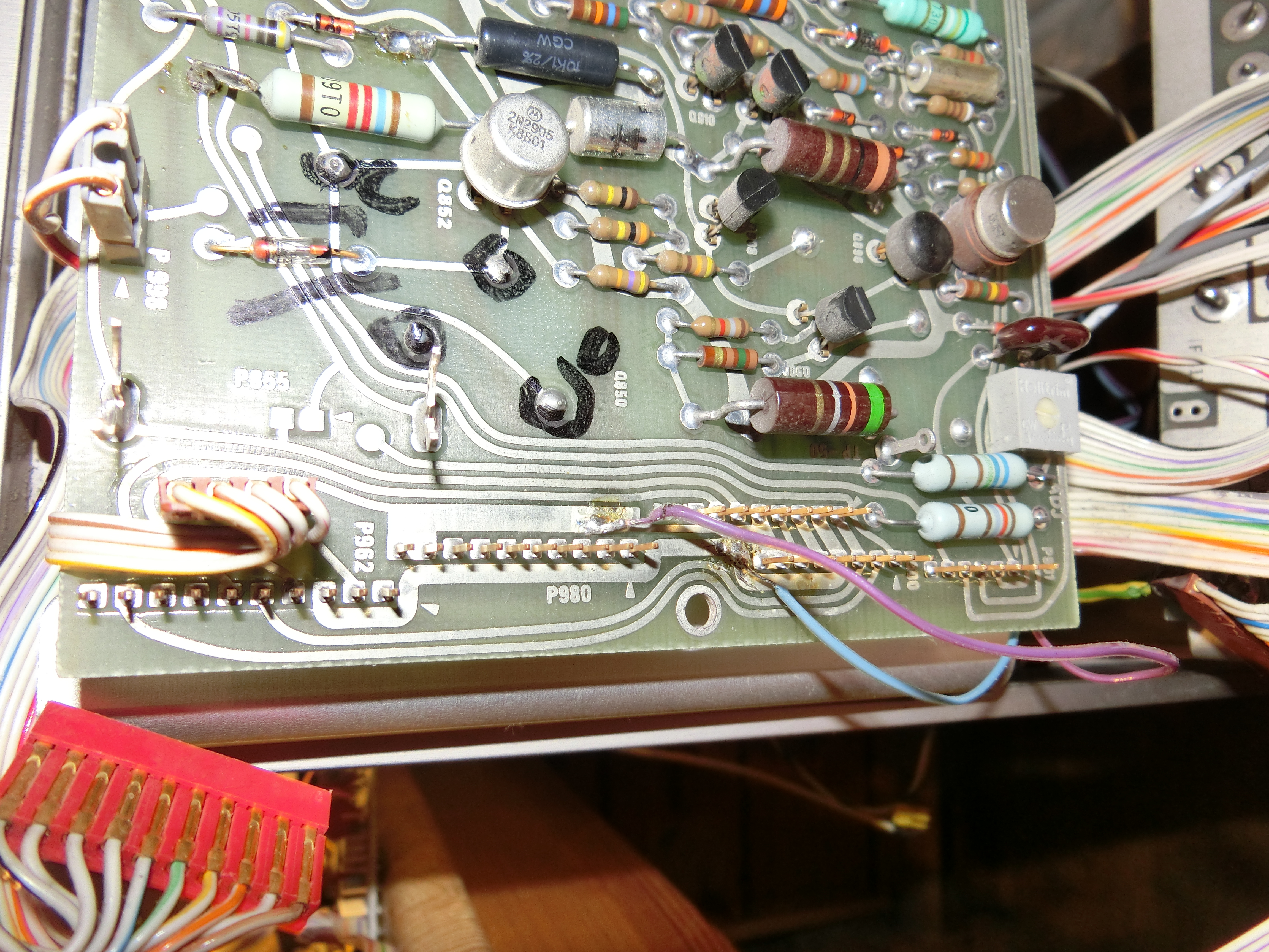
There was a "mystery wire" inside the 7623 from the LV supply board running to the plug-in-backpanel:
|
Starting at the Low Voltage Supply board
|
|
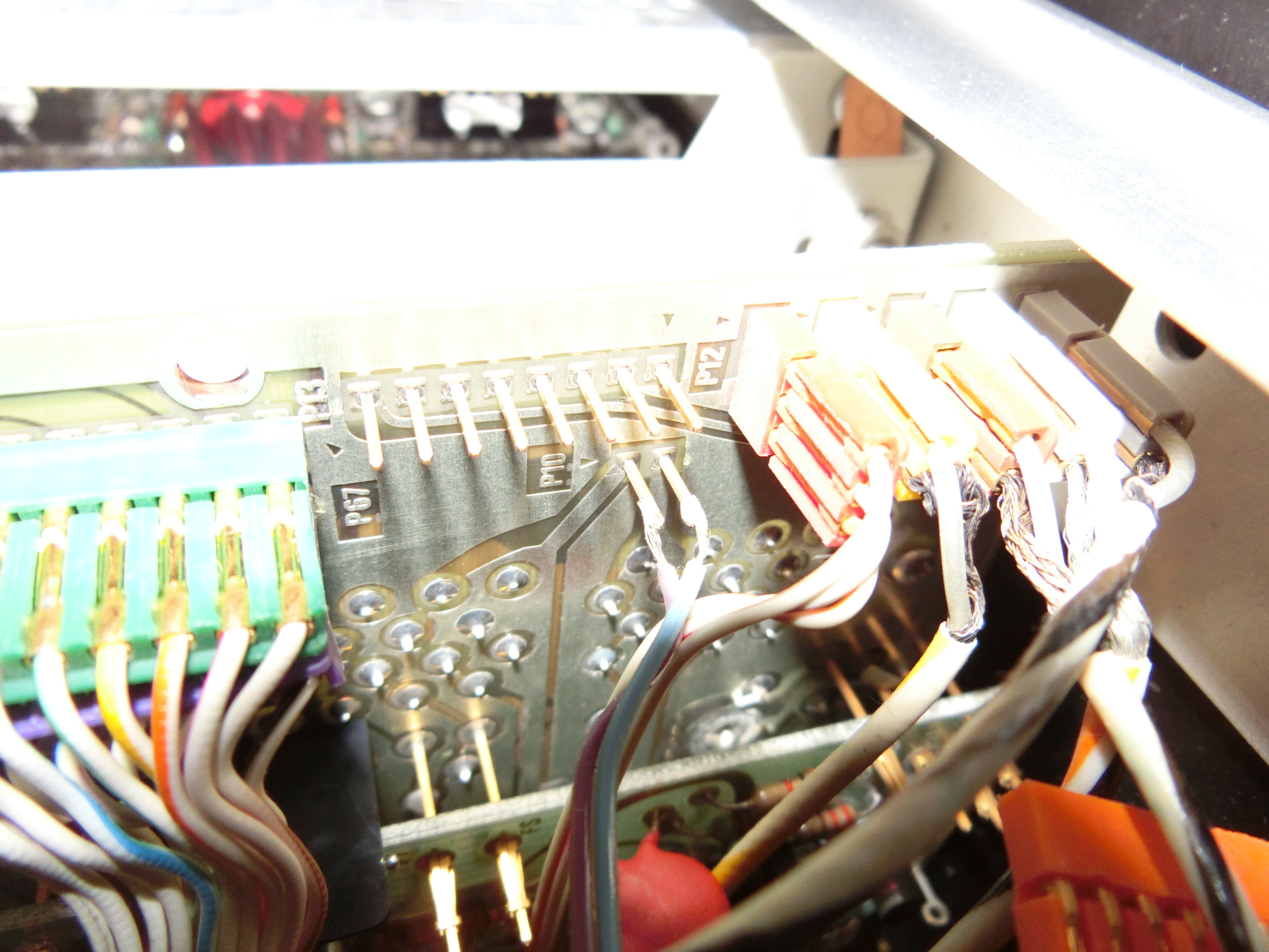
... up to P10 of the Main Interface Board:
P10 has following Pinout:
|
|
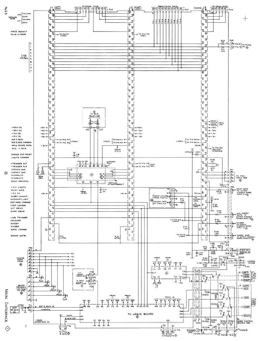
Schematic of the Main Interface Board |
|
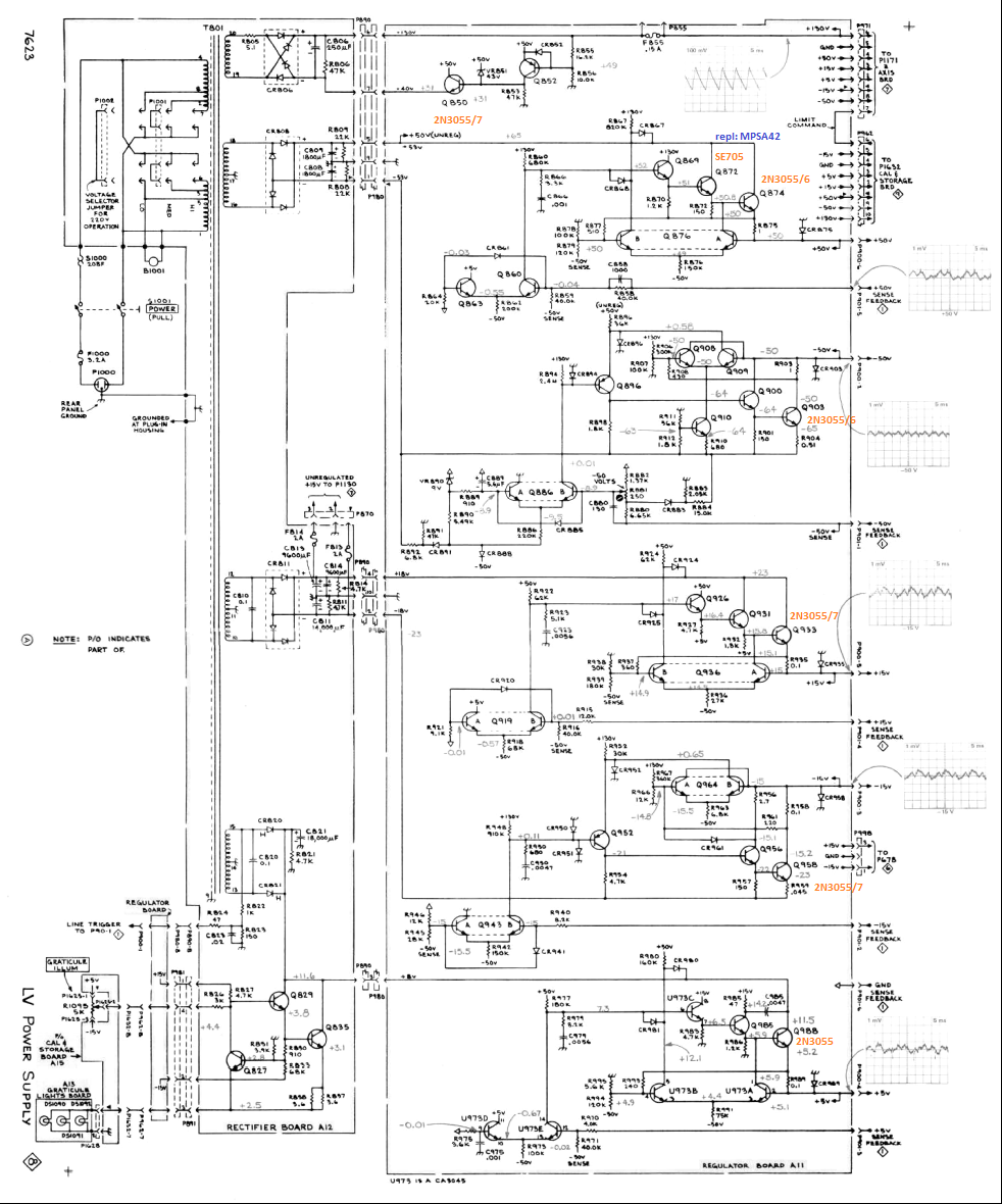
Schematic of the LV PS Board |
20.11.2015
To be sure, I ordered some of the more frequently used parts that were still available on AliExpress or wih Conrad:
- 2N5551 - 20 Pcs
- 2N2905 - 20 Pcs
- 2N2920 - 10 Pcs (dual transistor in TO39 package)
- CA3045 (transistor array in DIL14 package) - 3 Pcs
05.12.2015
The power transistors of the LV PS board are Tek special and 2 different part numbers but the service manual declares both of thiese parts as 2N3055 compatible.
However, testing them revealed the at least superficially OK (hFE between 40 and 100).
09.12.2015
Investigating the LV PS board showed Q872 to be blown. It being a SE7056 and no replacement type specified I thought a MPSA42 could also do the job. So I ordered 20 of these at Conrad.
18.12.2015
- MPSA42 have arrived
- replaced Q872 with an MPSA42. No improvement
- replaced Q869 with an 2N5551. No change.
- However, -50V produces output voltage, although too high (approx. -60V)
- I suspect a previous owner had it connected to 230V AC or 240V AC but the fine voltage selector was to the lowest of 3 settings.
26.12.2015
- -50V can be adjusted by R861 from -60V thru -52V, unfortunately not to -50V ...
- Page Tektronix 7623 Manual contains selected parts of the 7623's operators manual, also to be linked from other parts.
04.01.2016
- Re-Seating all Transistors on the LV-Supply Board Succeeded in completely working LV-Supply, HOORAY
- I had bought a bunch of CA3045 chips in case the one on the LV-Supply was damaged
- to check them, I replaced the CA3045 on the LV-Supply by one of the newly acquired => Works the same!
- HV-Supply works too ( having replaced the exploded Cap by a 22uF one) !
- after re-assembly, there are 4 connections unconnected because I did not document them at disassembly, DAMN!
- However, the CRT shows a beam, albeit out of focus
- Tracing the wires shows that two of the open connections are to go to the HV board, which is a pain in the backside because the HV-supply is so deep inside the oscilloscope
- One of the 2 connections, however, connects the focus-pot
- The other (P1245 of HV-Supply) connecting 600V to the Storage Control Board (A15)
- Unfortunately, connecting these 2 results resulted in:
- No CRT picure at all
- The HV-Supply case, doubling as the heatsink for the HV primary oscillator transistors, becoming unbearingly hot
- HV testpoint voltage dropping from ~614V (should be 700V according to manual) to 145V
- Disconnecting the cable from P1245 improved things: HV supply voltages back to normal, CRT beam back there, focus control working
- TODO: find out the cause of the error (most probably another shorted semiconductor)
05.01.2016
- Connected a Probe to the 7A18s inputs: Success!
- Voltage calibration seems to be off because 4V calibrator show up only as 3.6 divisions at 1V/Div amplifier setting
- Sweep frequency seems OK according to calibrator display
- Delayed Sweep looks OK
- Now to the 2 missing connections: Tracing finds:
- the longer, coax with blue/white coating connects to the "REMOTE ERASE IN" back panel connector, leading to P1764 on A15 - "Cal & Storage Circuit Board"
- the shorter, coax with green/white coating connects to J1047 - "EXT SS RESET IN" back panel connector, leading to P45 on A1 - "Main Interface Board"
- These resolved, there are 3 issues, put on the backburner for now:
- get storage to work, which is broken because of the short circuit in the 600V-line
- resolve the "miracle wire" issues. I removed the miracle wire because it seemed wrong
- readout does not work for the time being, root cause still unknown