Projekt TekRep7k: Unterschied zwischen den Versionen
Zur Navigation springen
Zur Suche springen
Keine Bearbeitungszusammenfassung |
Keine Bearbeitungszusammenfassung |
||
| Zeile 9: | Zeile 9: | ||
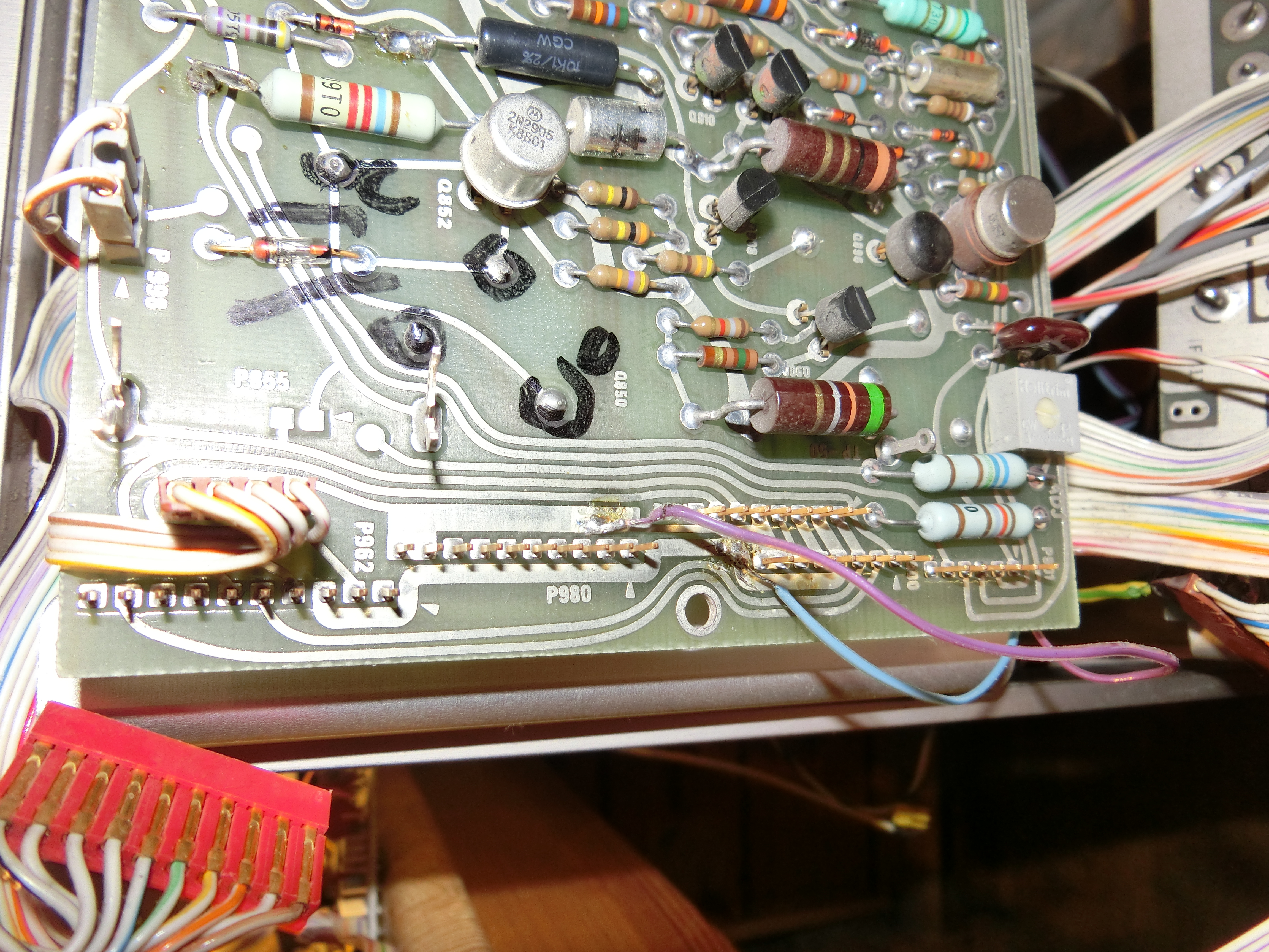
| {{T7623Img|Disassembly_Repair_HV-board_20151027/007_Start_Of_BotchedOn_Mystery_Wire.JPG|atts=height=300px}} | | {{T7623Img|Disassembly_Repair_HV-board_20151027/007_Start_Of_BotchedOn_Mystery_Wire.JPG|atts=height=300px}} | ||
| Starting at the Low Voltage Supply board | | Starting at the Low Voltage Supply board | ||
* blue wire from Pin #4 of Connector P900 - +5V | |||
* violet wire from Pin #7/8 of Connector P900 - GND | |||
|- | |- | ||
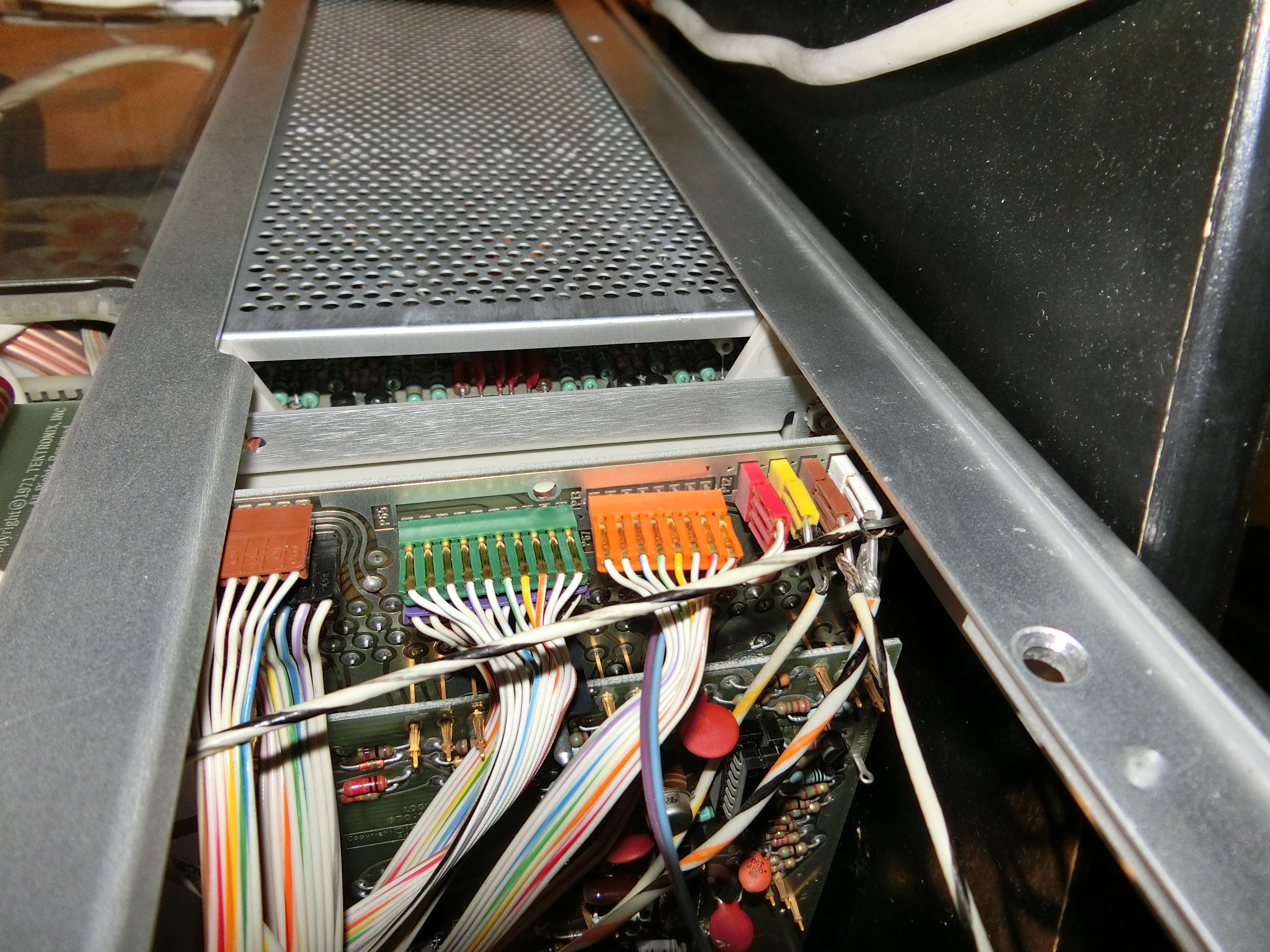
| {{T7623Img|Disassembly_Repair_HV-board_20151027/008_Trace_Of-Mystery_Wire.JPG|height=300px}} | | {{T7623Img|Disassembly_Repair_HV-board_20151027/008_Trace_Of-Mystery_Wire.JPG|height=300px}} | ||
| Zeile 14: | Zeile 18: | ||
|- | |- | ||
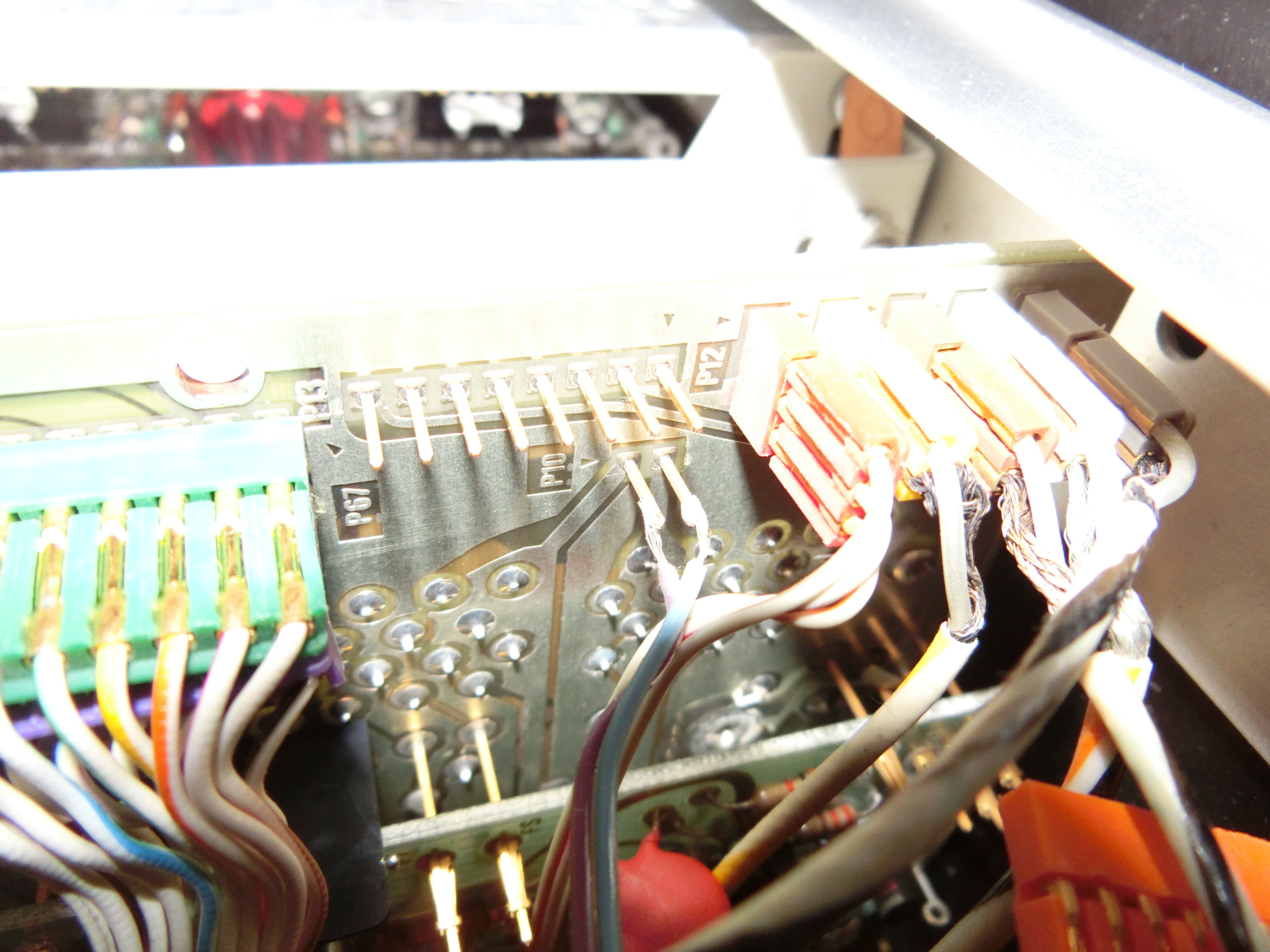
| {{T7623Img|Disassembly_Repair_HV-board_20151027/009_Destination_Of_Mystery_Wire_P10_of_Interconn_Board.JPG|height=300px}} | | {{T7623Img|Disassembly_Repair_HV-board_20151027/009_Destination_Of_Mystery_Wire_P10_of_Interconn_Board.JPG|height=300px}} | ||
| ... up to P10 of the Main Interface Board | | ... up to P10 of the Main Interface Board: | ||
* blue Wire to pin #2 of P10 | |||
* violet wire to pin #1 of P10 | |||
P10 has following Pinout: | |||
* Pin #1 (marked with triangle) - Pin 9A of all Plug-In Connectors, named "+5V Lights" | |||
* Pin #2 Pin 14A of all Plug-In Connectors, named "Lights Common" | |||
|- | |- | ||
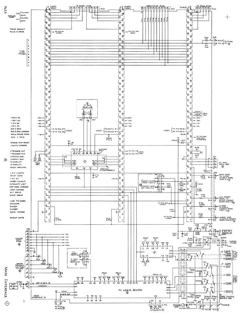
| {{T7623Img|Manual/Tek7623UsrManMainInterfaceSchematic.png|height=400px}} | | {{T7623Img|Manual/Tek7623UsrManMainInterfaceSchematic.png|height=400px}} | ||
Version vom 7. Dezember 2015, 21:19 Uhr
09.11.2015
There was a "mystery wire" inside the 7623 from the LV supply board running to the plug-in-backpanel:
|
Starting at the Low Voltage Supply board
|
|
snaking to the Main Interface Board |
|
... up to P10 of the Main Interface Board:
P10 has following Pinout:
|
|
Schematic of the Main Interface Board |
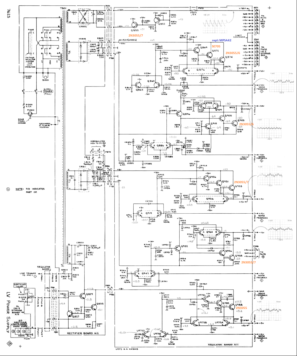
|
Schematic of the LV PS Board |