|
|
| Zeile 1: |
Zeile 1: |
| | {{Image|/public/public/Projekte/PUGAUGE/Hardware/PUGAUGE_BBD-002.JPG|height=400px}} |
|
| |
|
| The PUGAUGE is intended to be a base platform for devices to display Information in an environment where low power requirements are mandatory. | | The PUGAUGE is intended to be a base platform for devices to display Information in an environment where low power requirements are mandatory. |
| Zeile 9: |
Zeile 10: |
| | | |
| == Hardware == | | == Hardware == |
| | |
| | {{PUGAUGE}} [[PUGAUGE Hardware|Hardware]] consists of: |
|
| |
|
| * 8-Character Segmented LCD 14-segment Display | | * 8-Character Segmented LCD 14-segment Display |
| * Atmel AVR ATmega6490A AVR microcontroller | | * Atmel AVR ATmega6490A AVR microcontroller |
| | * Atmel ISP Connection |
| | * Arduino Upload Serial Interface |
| | * A Status LED on MCU port PB0 |
|
| |
|
| == Software == | | == Software == |
| Zeile 30: |
Zeile 36: |
|
| |
|
| {{tbc}} | | {{tbc}} |
|
| |
| == Build notes ==
| |
|
| |
| === Connection of ATmega6490 ===
| |
|
| |
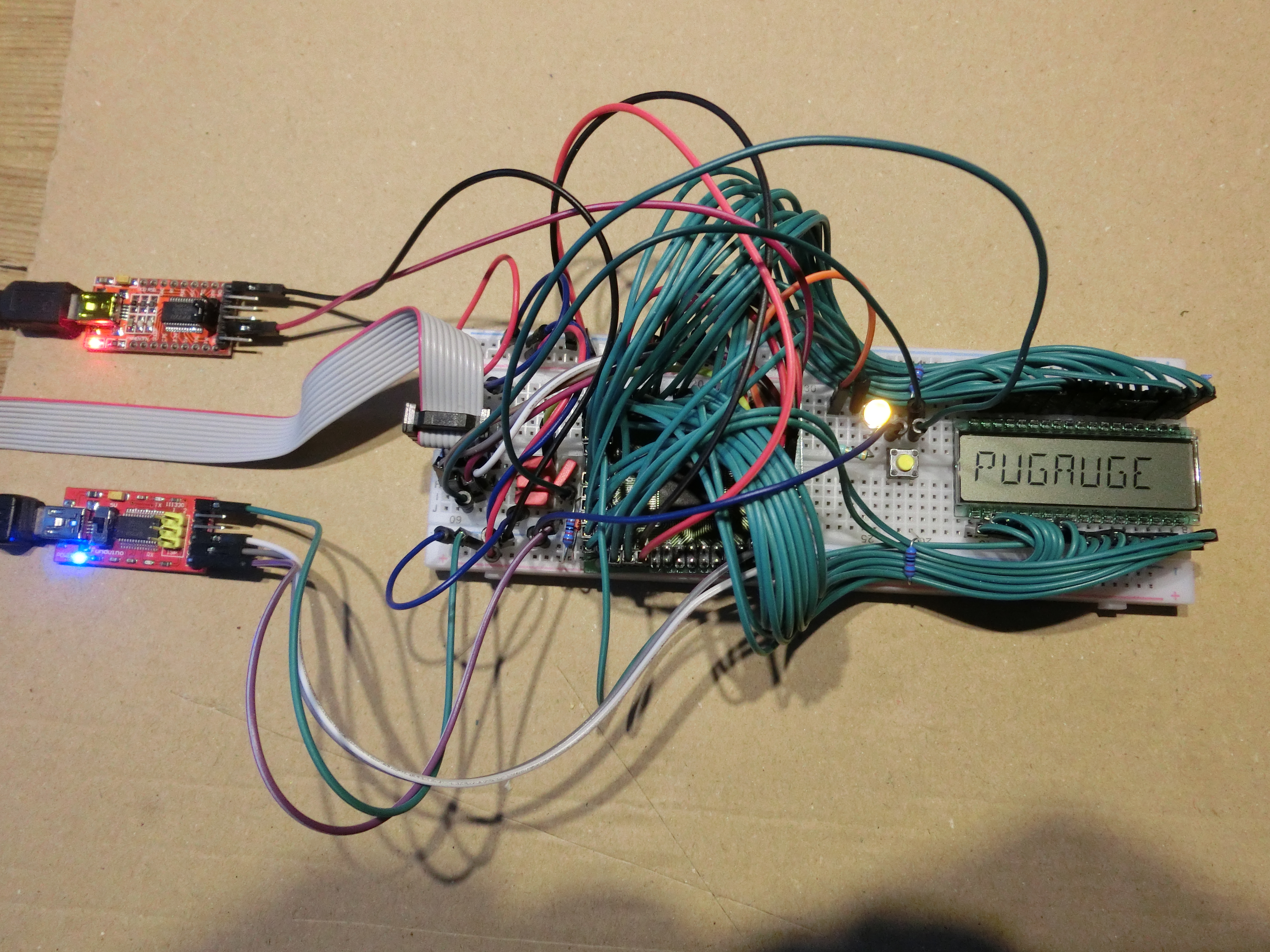
| In the first development version all circuitry is mounted on a solderless breadboard:
| |
|
| |
| {{Image|/public/public/Projekte/PUGAUGE/Hardware/PUGAUGE_BBD-002.JPG|height=400px}}
| |
|
| |
| * The ATmega6490 is mounted on the [[#TQFP-100 Breakout board|BBR]].
| |
| * LCD-Voltage Buffer Capacitor: 3x220nF FKC in parallel from ATmega6490 Pin 1 / BBR Pin 76 to GND
| |
| * System Status LED: Port line PB0 (ATmega6490 Pin 19 / BBR Pin 94) to 330 Ohm to yellow LED to GND
| |
| * In-System-Programmer (IST) USPasp connected to 10-pin 2x5 100mil-spaced Connector:
| |
|
| |
| See also http://nerdyelectronics.com/usbasp-tutorial/ :
| |
|
| |
| <pre>
| |
| Connector seen on board pins
| |
| USBasp pin number USBasp pin MCU Pin +---+---+---+---+---+
| |
| 1 MOSI MOSI | 2 | 4 | 6 | 8 |10 |
| |
| 5 Reset Reset +---+---+---+---+---+
| |
| 7 SCK SCK | 1 | 3 | 5 | 7 | 9 |
| |
| 9 MISO MISO +---+--++---++--+---+
| |
| 10 GND GND +-----+
| |
| 2 Vcc Vcc NOTE1: the USBasp ribbon cable has a RED marking on the wire going to in 1
| |
| thus, it should be on the LEFT side of above connector!
| |
| NOTE2: the USBasp ribbon cable connector has a protrusion in the near pin 5. Look for this to be sure!
| |
| </pre>
| |
|
| |
| {{TableBegin}}
| |
| ! Signal name !! description !! 10-pin-conn pin number !! ATmega6490 pin name !! ATmega6490 pin number !! BBR pin number
| |
| |-
| |
| | MOSI || data from programmer to MCU || 1 || MOSI || 21 || 96
| |
| |-
| |
| | Reset || reset pulse to MCU || 5 || Reset || 30 || 5
| |
| |-
| |
| | SCK || serial clock to MCU || 7 || SCK || 20 || 95
| |
| |-
| |
| | MISO || data from MCU to programmer || 9 || MISO || 22 || 97
| |
| |-
| |
| | GND || Ground reference || 10 || GND || 99,11,32,81 || 74,86,7,56
| |
| |-
| |
| | VCC || +5V supply from programmer || 2 || VCC || 100,10,31,80 || 75,85,6,55
| |
| {{TableEnd}}
| |
|
| |
| * Serial-USB Adapter, connected to TXD/RXD of UART0 of ATmega6490 PLUS Auto-Reset-Circuit using DTR of Serial-USB:
| |
|
| |
| {{TableBegin}}
| |
| ! Signal name !! description !! FT323-adapter pin !! ATmega6490 pin name !! ATmega6490 pin number !! BBR pin number
| |
| |-
| |
| | GND || Ground reference || GND || GND || ||
| |
| |-
| |
| | TXD || data from USB to MCU || TXD || RXD/PCINT0/PE0 || 2 || 77
| |
| |-
| |
| | RXD || data from MCU to USB || RXD || TXD/PCINT1/PE1 || 3 || 78
| |
| |-
| |
| | DTR || DataTerminalReady from USB || DTR
| |
| | 100nF Capacitor to "Reset"-Pin<br/>PLUS: pullup-10k-Resistor to +5V<br/>parallel to 1N4148Diode<br/>Cathode to +5V, Anode to Reset<br/>PLUS "RESET"Button to GND
| |
| | 30 || 5
| |
| {{TableEnd}}
| |
|
| |
| === TQFP-100 Breakout board ===
| |
|
| |
| When soldering the AVR6490 Chip in the TQFP-100 case to it's breakout board, I made an error:
| |
|
| |
| I turned it 90 degrees to the right. Therefore Pin 1 of the chip appears at Pin 76 of the breakout board.
| |
|
| |
| The algorithm to find the BBR pin when knowing the pin number on the TQFP-100 package of the ATmega6490 is:
| |
|
| |
| <code>''BBR-pin'' = (''TQFP-pin'' + 75) MOD 100</code>
| |
|
| |
| There will be a translation table on the [[PUGAUGE Tables]] page.
| |
|
| |
| Connection from the D301 LCD to the PUGAUGE MCU is documented on the [[PUGAUGE Tables]] page.
| |
|
| |
|
| == Font made visible == | | == Font made visible == |
|
| |
|
| Likewise, a graphic depiction of the 14-Segment font is to be found on the [[PUGAUGE Tables]] page. | | Likewise, a graphic depiction of the 14-Segment font is to be found on the [[PUGAUGE Tables]] page. |
The PUGAUGE is intended to be a base platform for devices to display Information in an environment where low power requirements are mandatory.
Examples are:
- Bike computers
- Thermometers
- mobile measurement devices
Hardware
PUGAUGE Hardware consists of:
- 8-Character Segmented LCD 14-segment Display
- Atmel AVR ATmega6490A AVR microcontroller
- Atmel ISP Connection
- Arduino Upload Serial Interface
- A Status LED on MCU port PB0
Software
Platform
The PUGAUGE is intended to be Arduino-compatible. The application software shall benefit from the ease of use, familiarity of many developers and availability of many libraries for sensors and other peripherals.
Therefore, an extension to the Arduino IDE is developed to allow the PUGAUGE being selected as a board type in the Arduino IDE. This should not be too complicated, as the PUGAUGE processor is an Atmel AVR processor closely related to the Atmel AVR processors used in the Arduino UNO and MEGA.
Additionally the optiboot bootloader for the Arduino is being modified to run on the PUGAUGE and allow Arduino sketches to be uploaded onto the PUGAUGE.(zu ergänzen)
Application
A special LCD library is being developed that provides easy access to the on board LCD ( 8 characters, 14 segments plus decimal point and apostroph).(zu ergänzen)
Font made visible
Likewise, a graphic depiction of the 14-Segment font is to be found on the PUGAUGE Tables page.