KV-1352 Video Input Hacking
The Sony KV-1352 CRT Color TV has no Component or CVBS video input.
However, there is an option enhancement "OPK-103" to add a "V-Board" into the KV-1352 which seems to provide Teletext-functionality. Additionally, the already present cut-out in the KV-1352s back case suggests potentially a SCART connector.
Nevertheless, I could not find hide nor hair about this miraculous "V-Board": there is no place to buy this board, not even hints to its part number, but also no documentation like functional description or schematic.
Therefore, let's try some reverse engineering in absence of the subject ...
Reverse Engineering the Video/CVBS/Component/SCART Connectivity
Extracting hints from the KV-1352 service manual
OPK-103 Teletext add-on mod
The KV-1352 Service Manual describes in chapter 2.6 adding the option "OPK-103" in the following (functional) steps (I added my interpretation of the effect these changes take on the TV):
- cut JW2 (wire link) on the M-board
- this leads to change input level on IC2 (M50120P) / Pin 24 (Mode2) from pulled down to ground to being pulled up, thus changing the remote control receiver from TV-mode to Text-mode
- new connections:
- V-1 - M-12
- M12-Signals:
- n/c
- GND
- nDATA from/to remote control receiver controller IC2 (M50120P)
- nDLIM from/to remote control receiver controller IC2 (M50120P)
- M12-Signals:
- V-2 - A-14(according to component side legend)
- A-14(component side legend)==A-13(solder side legend)-Signals:
- A-13(solder side legend AND schematic legend, 4-pin connector)
- 1 - Video
- 2 - GND
- 3 - n/c
- 4 - n/c
- A-14(solder side legend AND schematic legend)-Signals
- 7 - KILLER
- 6 - BLK - blanking
- 5 - HP
- 4 - SYNC
- 3 - VIDEO
- 2 - GND
- 1 - +12V
- V-4 - A-16
- A16-Signals
- 1 - IH-Delay out
- 2 - GND
- 3 - GND
- 4 - IH Delay in
- A16-Signals
- V-5 - A-11(according to component-side legend)
- A11-Signals
- 1 - GND
- 2 - R
- 3 - G
- 4 - B
- A11-Signals
- V-9 - F-7(according to component-side legend
- a closer inspection of my KV-1352 showed that the same connector labeled with "F-7" on the top/component side of the PCB is labeled with "A-6" on the bottom/solder side ??? ...
- (BTW: same seems to have happened with A15 (solder side) vs A-17 (component side), as well as A-16 (component side) vs. A-18 (solder side)
- F-7(component side legend)==A-6(solder side legend)-Signals (A-6 reference in the schematic)
- 1 - GND
- 2 - GND
- 3 - n/c
- 4 - +6V
- 5 - +14V
- 6 - n/c
- V-1 - M-12
What a possible Teletext decoder might do with these connections can be inferred from the Philips SAA5281ZP teletext Decoder Datasheet:
- gets CVBS input from the TV
- decode Teletext from the CVBS signal
- be controlled by an I2C or similar interface from the TV's remote control
- generate RGB text video rendering
ATTN: the synchronization mechanism for the display is still depending on the CVBS video signal processed in the base TV
The downside of this integration is that the RGB data from the text decoder cannot transport an sync information as the Teletext is displayed in sync with the video programme it is extracted from.
Soo, this seems to have been a dead end for now ...
OPK-102 "SCM Board" mod
There seems to be another modification, adding a mysterious "SCM board" to the KV-1352.
Not knowing what a "SCM board" is meant to be, I again resorted to the involved connections and other modifications when applying this mod:
- "SCM" may be "SECAM" or "SCART" (something has to use this SCART cutout in the back cover, please!)
- Disconnect A7 (normally connected to C-4)
- Remove R344/R345/R346 (33k) on A-board
- Remove R350 (100R)
- Remove JW-35 (next to R337, labeled "SECAM CUT") on A board
- Connect SCM Board
- SCM-4 - C-4 (before the modification A-7 is fed into C-4)
- SCM-5 - A-17(according to component side legend)
- A-17(component side)(==A-15(solder side)) signals
- 1 - GND
- 2 - PIC - picture control voltage from remote control receiver
- 3 - COL - colour control voltage from remote control receiver
- A-17(component side)(==A-15(solder side)) signals
- SCM-1 - A-18
- A-18(==A-16) signals
- 1 - IH-Delay out
- 2 - GND
- 3 - GND
- 4 - IH Delay in
- A-18(==A-16) signals
- SCM-3 - A-7
- A-7 signals
- 1 - n/c
- 2 - Blue channel
- 3 - Green channel
- 4 - Red channel
- 5 - +12V
- 6 - n/c
- A-7 signals
- SCM-2 - A-15 (according to component side legend)
- A-15(component side legend) == A-14(solder side legend) signals
- 1 - GND
- 2 - PIC - picture control voltage from remote control receiver
- 3 - COL - color control voltage from remote control receiver
- A-15(component side legend) == A-14(solder side legend) signals
Things learned from OPK-102 and OPK-103
None of the 2 above mods seems to incorporate a way of feeding an alternate CVBS or component signal into the TV-set.
Sadly, I could not find a hint as to how the SCART connector provided-for cutout is or can be made use of (this would have to include circuitry to disable video from TV receiver and to feed at least an external CVBS instead of the internally delivered CVBS fromn the tuner/IF-stage).
The dark side of mains connected electronics
On second thought the lack of external connections is not so unexpected because (and this is the reason for a word of WARNING!):
This TV-set is NOT insulated from mains !!!
Soooo, any galvanic connection from the outside would expose the user to possible mains voltage hazard !!
The only connections from / to the inside electronics are:
- The antenna connector on the back of the set (and the internal telescopic antenna)
- the 2 3.5mm headphone jacks on the side of the front bezel
For these 2 connections precautions have been taken to protect the human user:
- the antenna connector is galvanically decoupled from the chassis by a set of 3 parallel capacitors, which are not even placed on the main electronics board, but on a separate PCB inside the antenna/RF-input connector assembly.
- the audio output to the speaker and the headphone connectors (one switching off the speaker and the other not switching off the speaker) are isolated from the chassis by an isolation transformer which is placed not on the main PCB (A) but mounted on the inner chassis on the CRT
Any additional external electrical connection MUST also be galvanically isolated (according to law at least capable of withstanding 1500V across the isolation) from the TVs internal circuitry.
So, what to now now ?
So, there is no pre-described modification to feed CBVS or component video in the KV-1352.
Possible CBVS modification
A modification to feed CVBS into the KV-1352 must incorporate 4 features:
- find the place where CVBS is inside the KV-1352
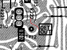
- this is the collector of transistor Q202 on the A-board (conveniently available on test point
TP12): 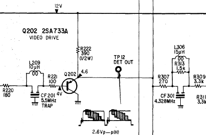
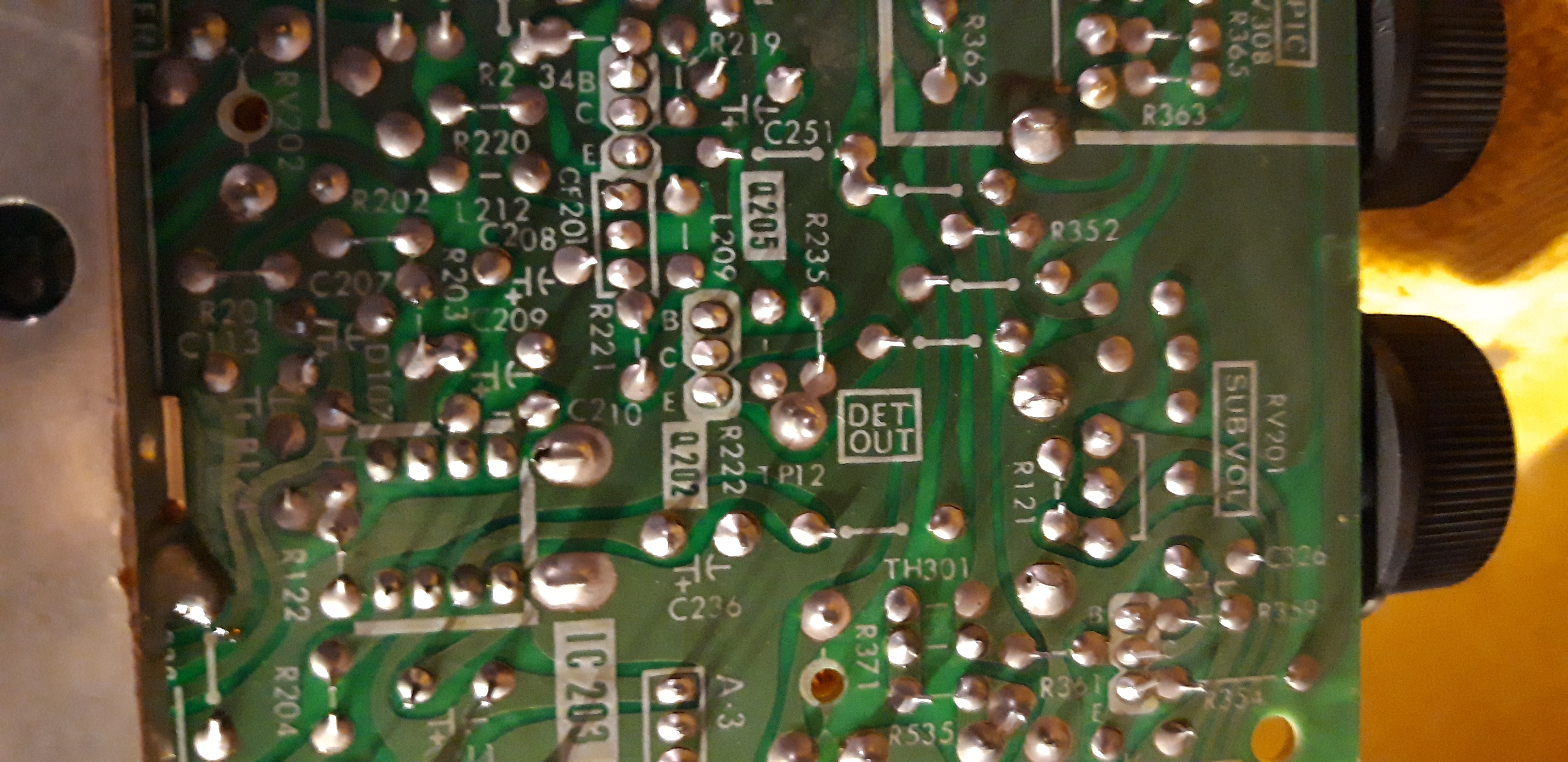
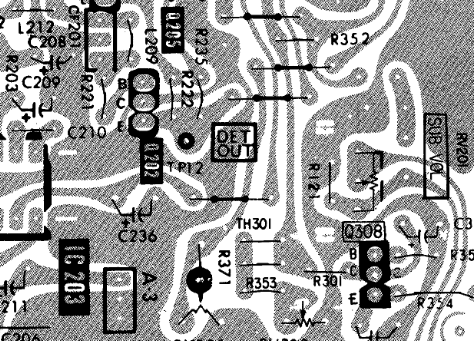
- this is the collector of transistor Q202 on the A-board (conveniently available on test point
- find a method to switch between internal video and external video
- ideally, the KV-1352s video IF processor could be coaxed into providing no signal
- unfortunately, OPK102 and OPK-103 do not help here because they both do not need to switch between tuner and another video source
- if all else fails, a mechanical switch shall be used to cut the connection from Q202's collector to TP12/R307
- cut the connection between the Video driver stage around Q202/R222+TP12 and the downstream circuitry (cut along the red line):
- galvanically isolate the input signal from the internal electronics
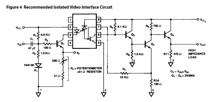
- an opto-isolator with the necessary bandwidth must be used PLUS the galvanically isolated power supply for the circuitry driving the input side of the opto-isolator
- video opto-isolator: Broadcom HCNW4562 - 5pcs HCNW4562-000E - DIP8 ordered at digikey with DigiKey Order 72796786 at NOV-12, 2021
- power isolator: B1212S-1W - AliExpress Artikel 4000891973346, ordered with AliExpress Order 8141715219203825
- adapt the input signal (normal 1Vpp video signal level) the the internal level (2.6Vpp)
- this should be possible by biasing the output transistor of the opto-isolator circuit equivalent to Q202, the hcnw4562's recommended application circuit should allow for tuning the level: